V3 INSTALLATION GUIDE
Foreword
JBC provides suspension components to support the installation of rack and pinion steering into the Datsun PL510. The components are designed with complimentary suspension points to produce favorable suspension geometry in a lowered car. The kit is not completely bolt-in and will require additional parts and modifications. Given the vast amount of aftermarket parts available for these cars JBC does not guarantee our components will work effortlessly with all possible suspension combinations.
Have a question about your specific setup? Ask us, we are here to help.
In this guide we will go over the installation of all of the V3 JBC rack and pinion components including the JBC steering column. If you plan to complete a DIY steering column, please refer to the V2 install instructions for a suggested steering column setup.
Please read through the entire installation guide before getting started on your project.
Preparation
Before getting started, gather all of the parts needed for the portions of the complete assembly that you plan to install.
Parts available from JBC:

Rack and Pinion Crossmemeber
Includes crossmemeber, steering arms, frame washers, LCA spacer, and necessary hardware.

Motor Mounts
Adapt our crossmember to fit your motor
Parts that need to be sourced elsewhere:
A steering rack from a Ford MK2 Escort (1975-1981). The V3 JBC crossmember is made to fit only the Escort rack not MR2/AE86 racks that we used in V1 and V2. The Escort racks are available new and there are many steering ratio's available.
Important! we use the rack in backward orientation so, a rack advertised for a RHD Escort will be needed to fit a LHD 510 and visa versa. Also, The ratios are sold with steering ratios advertised as installed in an Escort. In order to know the steering ratio when installed with the JBC steering arms in a 510, multiply the advertised steering ratio by 0.84
We like to get ours at Motorsport-tools.com but there are many vendors and manufacturers to choose from.Here are a few examples:
For most builds these will work perfectly. They are the cheapest option but we have been more than satisfied with the quality of the 10 or so we have had in our hands. We are told they could bend on rally cars though.
LHD 2.4 ratio when used in JBC kit
LHD 2.0 ratio when used in JBC kit
RHD 2.0 ratio when used in JBC kit
Heavier Duty and made in the U.K. these racks are upgraded in size and can handle any abuse. They are a tad larger overall and so they are a tighter fit in the crossmemeber mounts and may require mallets, trimming of flashing, sanding of bushings.
LHD 2.0 ratio when used in JBC kit
LHD 1.8 ratio when used in JBC kit
RHD 2.0 ratio when used in JBC kitUnfortunately, we have seen some quality concerns with the casting end. The rack tube seems to not always be centered in the casting which results in a slight angle when mounted in the crossmemeber. If you notice this let us know and we can discuss options.
Avoid these "competition spec" racks. It isn't advertised well but they are 35mm longer than stock and this will compromise the JBC designed geometry. Look out for other extended racks from other vendors/manufacturers as well.

Rack bushings to match the escort rack, some racks come with them, some are sold separately.
We have found that there is a big variation in rack castings as well as bushing dimensions, even though they are all sold as stock replacements. This means that it was difficult to size the clamp openings and some combinations may be extra tight while others may need to use a shim (included) to make it tighter.The inner tie rods match the MK2 Escort rack and are usually sold pre-installed on the rack units.
Two outer tie rods from a '86-'89 SAAB 900. These are available from any parts store with MOOG being our preferred brand.
Moog #ES2132RL

Two ball joints from a 1972 Datsun 510. Early model years came with a smaller ball joint taper and will not fit the JBC steering knuckles. Only the correct large ball joints are available new from many auto parts suppliers.
Moog #K9011

Two motor isolators from a 1989-1998 Nissan 240sx for use with all JBC motor mounts.
These are available new from auto parts suppliers or are usually easy to find used.

If installing an L-series motor, the motor will need to be converted to front oil sump. This can be done with an oil pan and oil pick-up tube from a 1978-1979 Datsun 200SX or 510.
Recommended modifications:
There are an endless amount of possible suspension combinations given the number of aftermarket and OEM parts that can bolt on to these cars. This makes it is impossible to design for every possible suspension configuration. JBC assumes the following list of modifications have been completed in order to install our components and see our predicted suspension characteristics. Installation is still possible without these modifications but the resulting steering will be different than ours by some small amount.
Be aware that the location of the LCA pivot point on the JBC crossmember will result in a wider track width compared to the stock crossmember if the same LCA length is used. Without changing the LCA length to compensate this will result in different wheel fitment in the fenders. Typically, there will be about 10mm of increased width on each side but, the exact amount will vary depending on setup.
Added wheel caster angle by pulling the wheels forward 30mm. This can be done with many companies adjustable TC-rods, some even though adjustable may have to be modified.
Added wheel caster by pulling the top of the strut back 25mm. This can be done with many companies adjustable strut top hats.
Roll center spacers (bump steer spacers) between the strut and steering knuckle. The designed spacer height is 32mm.

Lowered ride height. The ride height of a car affects the final tie-rod lengths when the car is aligned. This in turn affects the steering geometry of the car. The designed ride height is such that the LCA makes a 4 degree angle to the ground

It is also important to know that any components that modify the suspension points in ways not outlined here will have negative effects.
Specifically, the ball joints (pivot and height) and TC-rod pivots are intended to remain stock. The TC-rod is less critical, the ball joint can cause drastic changes. Beware that some aftermarket LCA’s on the market use extra large ball joints.
For example, the T3 GTX2 LCA’s have ball joints that are 20mm taller than the stock ball joint. The below chart shows the results of using such ball joints. It shows the drastic toe out bump steer induced by using this setup as compared to many other part combinations using the stock ball joint. Not recommended.

Suspension Installation:
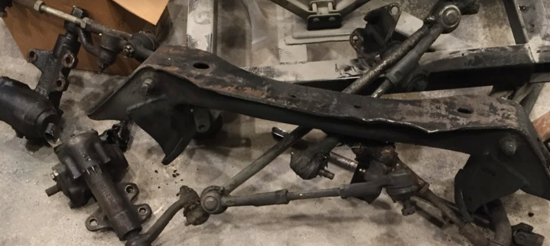
1)
First the old steering components need to be removed. If the engine is still in place, suspend or support the engine from below in a safe way so that the old components can be removed. Remove the original crossmember, steering box, steering column, drag link, idler arm, tie-rods, and steering knuckles. You should have a pile of junk similar to shown below. The only part that will be reused is the stock steering column, do not damage or bend this component. Send the column to JBC for the core charge refund or hold it aside for a DIY column install.
2)
Next, mount the steering rack into the JBC crossmember. This is harder to do with a motor in the way so, it’s better to do before putting the crossmemeber in the car.

We have found that with all of the options for bushings and different rack manufacturers, some combinations can end up crooked when mounted. To help correct this if it occurs we have begun including a bent shim with the kit. Early kits had flat shim for the same purpose. Typically the U-shape shim will be used under the bushing on the passengers side for the regular duty rack option shown above. The heavy duty options usually use no shims.

It can sometimes be a tight fit, this is great for performance but can make it difficult to install. Lubing the bushings helps a lot. Also a couple wraps of electrical tape to hold the bushing together where it is cut can reduce frustration.

3)
Loosely install the motor mounts on the crossmember with the provided hardware. Also, Loosely install the motor isolators on the motor side mounts.

4)
Slowly, raise the crossmember assembly into place under the car. Guide the motor isolators into the crossmemeber motor mounts. Align the crossmemeber mounting holes with the frame mounting holes. Screwdrivers can be used in each set of holes to guide the rack alignment as it is raised. Then, clamp the crossmember in place between the bolt holes to make bolting up easier. Check for any clearance issues with the rack. An L motor oil pan will need to be dented slightly to clear the left hand side rack clamp, as shown below. An SR20DET oil drain may need to be modified to make clearance in this same area.

5)
Secure the rack in place with the provided hardware and new frame washers. The bolt heads should be oriented down as shown, this reduces the chances of the LCA clashing with the bolt end.

6)
Finish aligning the motor isolators and lower the motor onto the mounts. When satisfied with placement, tighten the motor mounts and isolators in place.
7)
Next, find the position for the LCA on the inner LCA pivot bolt. It is critical that there is not undue stress on the LCA, TC-rod, or connection points. These components should be mounted in a free moving and natural position. Do not force suspension components into place. A stock LCA or aftermarket/custom adjustable LCA with Heim-joint can be used.
The LCA bolt we use is 14mm diameter, the stock 510 LCA bolt is 14.3mm. For parts that bolt to the stock LCA bolt, there will be 0.3mm of clearance which will seem to rattle when loose. This is not an issues when the the LCA bolt is torqued the clamping force will secure the pivot. The possible 0.15mm offset of the pivot from nominal is negligible to the steering.

DIY adjustable LCA kit as shown available from JBC
If using a stock LCA, the point of material on top of the pivot will need to be trimmed as shown below in order to clear the motor mount surface of the new crossmember.

With the TC-rod connected to the front of the car, bolt the LCA to the TC-rod.
Now, move the LCA inner pivot in line with the crossmemeber LCA pivot point and insert the supplied bolt. Let the LCA sit in its natural front to back position along the bolt. Measure the space on the bolt in front of and behind the LCA/Heim-joint. If using Heim-joint high-misalignment bushings or similar spacer, be sure to install these on the bolt during measurement as well.

If using aftermarket parts with a pivot point at the LCA / TC-rod connection, you will be able to move your pivot point anywhere along the bolt. We recommend trying to keep the LCA perpendicular to the center of the car. As a point of reference, the LCA moved all the way to the back of the bolt is approximately the front-to-back position of the stock LCA pivot. In case you’re natural LCA position is not between the crossmemeber front and back plate. It is possible to oversize the LCA to TC-rod mounting holes slightly to give some adjustment.
8)
Cut the LCA spacer material to fill these spaces. Flush cuts are desirable, use machinery if available. Although, a bit of care and a simple hack saw will do if need be.
Bolt the LCA into the crossmember using the provided hardware and the fabricated spacers. Be sure to put the bolt head in the rear of the crossmemeber. The nut and extra bolt length may interfere with the rack and boots.

9)
With the ball joints installed on your LCA, install the JBC shortened steering knuckles on the ball joints as shown using the stock ball joint castle nut.

10)
Install the inner tie-rods on the rack if they are not already. Install the outer tie-rods onto the inner tie-rods. Use the stock outer tie-rod nyloc nut to install the outer tie-rod in the JBC steering knuckles.
11)
Bolt the steering knuckle to the bottom of the roll center spacer and into the strut.
12)
If not already, remove the stock lower steering column shaft from your car.
13)
Next is the only modification needed to install the JBC column. Skipping this step is unsafe and could result in your column coming loose during driving.
Cut 20mm off of the overall length of the steering column housing tube.
Then, Cut a 15mm-20mm slit in the top and bottom (or side to side, they just need to be 180 degrees apart) of the stock steering column housing as shown. The slit will allow the housing to be compressed onto the ball bearing we install and holds it in place. The 35mm two piece shaft collar is used for the compression. A cut-off wheel works well for this task.
This can easily be done in place if there is no engine installed but the housing may need to be removed if there is not enough working room.

14)
Take the JBC steering column and insert the splined shaft into the column.
IMPORTANT: There are differences in the spline location between early and late 510's. This is why you may have been asked which you have when ordering. This means that the incorrect column installed can be unsafe and result in poor spline engagement. You must check this as follows. When inserting the column feel for when the splines begin to engage and mark the position of the end of the housing on your shaft. Measure this mark to the end of the nylon bushing. This length should be between 25mm-50mm, more or less than this range is unacceptable. If out of range please contact JBC, either we sent you an incorrect part or the upper column installed in you car doesn't match the year of your car. If you ordered your column in 02/19 or later then you likely have our new custom made universal column that does not have this problem. This shaft has a much longer spline length than the stock column you pull out.
Now continue to insert the shaft until it is in it's final location with the bearing centered in the slots just cut.

Then engage the lower U-joint onto the steering rack. The lower joint should be clocked to the upper joint as shown to best cancel out the U-joint non-linearity's. (Not doing so will result in the wheels turning faster/slower at different steering angles.)

15)
Position the 35mm shaft collar such that the split in the collar is aligned with the slit in the column tube. The collar should also be positioned directly over the bearing. Tighten the collar in place. The steering column should now be tightly secured and unable to be pushed in or pulled out while still being free to rotate.

16)
Once the column is fully in position, install and tighten the U-joint bolts. Now before putting the car on the ground move the steering through the full stroke. We have had some installs that felt like they had a hard spot in the steering. This seems to be just having a u-joint tightened up while not in it’s natural position. We have always solved this by moving the steering wheel to the hard spot. Loosening the u-joint bolts, tapping them to shake them into their natural location and then tightening the bolts back up.
17)
Center the steering wheel and check that all the components and bolts installed in these instructions are tight and ready to drive.
18)
Complete a wheel alignment to your desired settings and check that all adjusted components are tight.
You should now have a smooth, reactive steering setup with JBC suspension geometry providing predictable and stable handling.
We sincerely hope you enjoy your ride as much as we do.
If you have any further question, comments, or feedback don’t hesitate to contact us.
If you are interested in how we arrived at our suspension design take a look at our Suspension Design Page.
Happy racing. Be safe.
-JBC