V2 INSTALLATION GUIDE
IMPORTANT UPDATE
It has been brought to our attention that the V2 rack mount bushings are not holding up as well as we would like under high loads. Specifically, the power steering racks have been shown to make enough force to cause failure. You should have been contacted about receiving an upgrade kit to fix this issue. The kit replaces the over-sized JBC bushings originally supplied with the kit, with stock Toyota style bushings and metal inserts to fill in the remaining space and interlock the rack casting to the rack. We manufacture and ship the parts with new bushings at no cost to you so please contact us if you did not receive a kit. While only some applications may ever develop the issue, we would like to see all V2 kits get the upgrade. There is a section below that covers how to install the upgrade. As always if you have any further questions please don't hesitate to ask.
Foreword
JBC provides suspension components to support the installation of rack and pinion steering into the Datsun PL510. The components are designed with complimentary suspension points to produce favorable suspension geometry in a lowered car. The kit is not completely bolt-in and will require additional parts and modifications. Given the vast amount of aftermarket parts available for these cars JBC does not guarantee our components will work effortlessly with all possible suspension combinations.
Have a question about your specific setup? Ask us, we are here to help.
In this guide we will go over the installation of all of the JBC front suspension components and a suggested steering column setup. The steering column is the most fabrication intensive part of the installation. It requires cutting and welding of steering components. If you are not comfortable completing these steps yourself, we recommend taking your parts to someone capable and trusted to do the work.
Please read through the entire installation guide before getting started on your project.
Preparation
Before getting started, gather all of the parts needed for the portions of the complete assembly that you plan to install.
Parts available from JBC:

Rack and Pinion Crossmemeber
Comes with frame washers, LCA spacer material, rack bushings, rack clamps and necessary hardware.

Shortened Steering Knuckles
For use in combination with JBC crossmemeber, not reccomended for use with stock setup.

Motor Mounts
Are you installing a motor that we do not provide mounts for? Let us know; we may be interested in designing parts for you.
Parts that need to be sourced elsewhere:
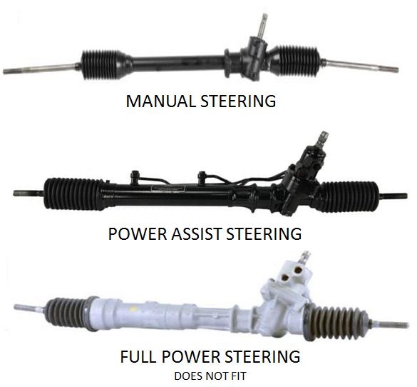
A steering rack from a Toyota AE86 Corolla 1983-1986 or Toyota AW11 MR2 1984-1989. The JBC crossmember is made to fit only manual and power-assist racks. The full power racks do NOT fit, they are easily identified by their completely cast aluminum housings as shown.
Two inner tie-rods from…
-a 1998-2005 Lexus GS 300, if installing with a shorter than stock length LCA’s

OR
-a 1985-1988 Toyota Cressida, if installing with a stock length or longer LCA’s
Note: T3 GTX2 LCA's will require these tie rods
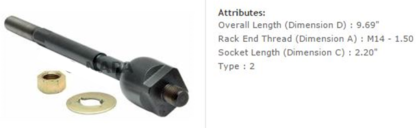
Getting the correct inner tie-rods ensures that there is sufficient thread engagement between the inner and outer tie-rods during final alignment. Both tie-rods are available new from many auto parts suppliers.
New inner tie-rod boots are recommended to protect the new inner tie-rods.
Two outer tie-rods from a 1972 Datsun 510.
Both outer right hand side if using the Lexus inners. The Lexus inners both have right hand threads.
If using Cressida inners you can use both right hand sets or a right and left hand set, your choice.
These are available new from many auto parts suppliers.

Two ball joints from a 1972 Datsun 510. Early model years came with a smaller ball joint taper and will not fit the JBC steering knuckles. Only the correct large ball joints are available new from many auto parts suppliers.

Two motor isolators from a 1989-1998 Nissan 240sx for use with all JBC motor mounts.
These are available new from many auto parts suppliers.

If installing a 4 cylinder L-series motor, the motor will need to be converted to front oil sump. This can be done with an oil pan and oil pick-up tube from a 1978-1979 Datsun 200SX or 510.
Parts for the suggested column install:
One steering column universal joint and intermediate shaft from an 80’s Toyota Corolla. Make sure to match the style rack you are installing. If you have a power rack get a power column or if you have a manual rack then get a manual column. The rack shaft splines are different and need to match. Some joints and shafts are available new from various auto parts suppliers.

A clamping 2-piece shaft collar for a 35mm shaft.
One supplier of these is McMaster.com they have several material options. We like PN: 9520T17 made of 2024 aluminum for its corrosion resistance and low cost.

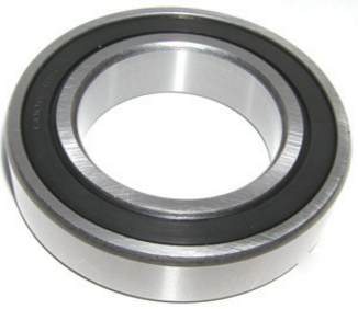
A ball bearing for the steering column
-If NOT USING the JBC column bushing, a bearing with 15mm internal diameter and 32mm outer diameter is required. There are many possible options for this fit. One supplier of these is McMaster.com they have many options.
We like PN: 5972K83 for its lubrication and double seal design.
-If USING the JBC column bushing, a bearing with 20mm internal diameter and 32mm outer diameter is required. There are many possible options for this fit. One supplier of these is McMaster.com they have many options.
We like PN:5972K279 for its lubrication and double seal design.
Two shaft collars for 15mm shaft size with an outer diameter less than 30mm. One supplier of these is McMaster.com they have several options. We like PN:57485K72.

Recommended modifications:
There are an endless amount of possible suspension combinations given the number of aftermarket and OEM parts that can bolt on to these cars. This makes it is impossible to design for every possible suspension configuration. JBC assumes the following list of modifications have been completed in order to install our components and see our predicted suspension characteristics. Be aware that the location of the LCA pivot point on the JBC crossmember will result in a wider track width compared to the stock crossmember if the same LCA length is used. Without changing the LCA length to compensate this will result in different wheel fitment in the fenders. Typically, there will be about 10mm of increased width on each side but, the exact amount will vary depending on setup.
Added wheel caster angle by pulling the wheels forward 30mm. This can be done with many companies adjustable TC-rods, some even though adjustable may have to be modified.
Added wheel caster by pulling the top of the strut back 25mm. This can be done with many companies adjustable strut top hats.
Roll center spacers (bump steer spacers) between the strut and steering knuckle. The designed spacer height is 32mm.

Lowered ride height. The ride height of a car affects the final tie-rod lengths when the car is aligned. This in turn affects the steering geometry of the car. The designed ride height is such that the LCA makes a 4 degree angle to the ground

It is also important to know that any components that modify the suspension points in ways not outlined here will have negative effects.
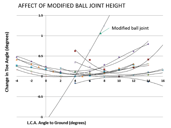
Specifically, the ball joints (pivot and height) and TC-rod pivots are intended to remain stock. The TC-rod is less critical, the ball joint can cause drastic changes. Beware that some aftermarket LCA’s on the market use extra large ball joints.
For example, the T3 GTX2 LCA’s have ball joints that are 20mm taller than the stock ball joint. The below chart shows the results of using such ball joints. It shows the drastic toe out bump steer induced by using this setup as compared to many other part combinations using the stock ball joint. Not recommended.
Suspension Installation:
1)
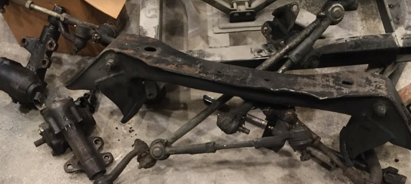
First the old steering components need to be removed. If the engine is still in place, suspend or support the engine from below in a safe way so that the old components can be removed. Remove the original crossmember, steering box, steering column, drag link, idler arm, tie-rods, and steering knuckles. You should have a pile of junk similar to shown below. The only part that will be reused is the stock steering column, do not damage or bend this component.
2)
Next, mount the steering rack into the JBC crossmember using the provided bushings and hardware. This is hard / impossible to do with a motor in the way so, it’s better to do before putting the crossmemeber in the car.

2.b.) Bushing upgrade install
Included in your upgrade kit:
-Rectangular steel inserts (Power steering kits only have one)
-Steel top clamps
-New bushings, Stock Toyota style replacements (Power steering bushings different than pictured)

Manual steering kit pictured, power steering kit varies slightly
1. Remove old rack and bushings if already installed.
2. Install bottom rectangular steel inserts. The one with a rectangle cut-out goes on the driver’s side. If manual steering, then you will have another with round cut out for the other side.
(Be sure you have them on the correct side, removal won’t be fun.)

Some persuasion may be needed to fully seat the inserts, press fit is expected.
3. Install the new bushings on your rack. We recommend lubing the outside of the bushing for easier fitment.

There’s no such thing as too much.
4. Finally, seat the rack with bushings into the crossmember and bolt on the new steel top clamps.
The two clamps have different size cutouts, match them to the bushing sizes.

Fully installed kit
3)
Loosely install the motor mounts on the crossmember with the provided hardware. Also, Loosely install the motor isolators on the motor side mounts.

4)
Slowly, raise the crossmember assembly into place under the car. Guide the motor isolators into the crossmemeber motor mounts. Align the crossmemeber mounting holes with the frame mounting holes. Screwdrivers can be used in each set of holes to guide the rack alignment as it is raised. Then, clamp the crossmember in place between the bolt holes to make bolting up easier. Check for any clearance issues with the rack. An L motor oil pan will need to be dented slightly to clear the left hand side rack clamp, as shown below.

5)
Secure the rack in place with the provided hardware and new frame washers. Th bolt heads should be oriented down as shown, this reduces the chances of the LCA clashing with thte bolt end.

6)
Finish aligning the motor isolators and lower the motor onto the mounts. When satisfied with placement, tighten the motor mounts and isolators in place.
7)
Next, find the position for the LCA on the inner LCA pivot bolt. It is critical that there is not undue stress on the LCA, TC-rod, or connection points. These components should be mounted in a free moving and natural position. Do not force suspension components into place. A stock LCA or aftermarket/custom adjustable LCA with Heim-joint can be used.

If using a stock LCA, the point of material on top of the pivot will need to be trimmed as shown below in order to clear the motor mount surface of the new crossmember.

With the TC-rod connected to the front of the car, bolt the LCA to the TC-rod.
Now, move the LCA inner pivot in line with the crossmemeber LCA pivot point and insert the supplied bolt. Let the LCA sit in its natural front to back position along the bolt. Measure the space on the bolt in front of and behind the LCA/Heim-joint. If using Heim-joint high-misalignment bushings or similar spacer, be sure to install these on the bolt during measurement as well.

If using aftermarket parts with a pivot point at the LCA / TC-rod connection, you will be able to move your pivot point anywhere along the bolt. We recommend trying to keep the LCA perpendicular to the center of the car. As a point of reference, the LCA moved all the way to the back of the bolt is approximately the front-to-back position of the stock LCA pivot. In case you’re natural LCA position is not between the crossmemeber front and back plate. It is possible to oversize the LCA to TC-rod mounting holes slightly to give some adjustment.
8)
Cut the LCA spacer material to fill these spaces. Flush cuts are desirable, use machinery if available. Although, a bit of care and a simple hack saw will do if need be.
Bolt the LCA into the crossmember using the provided hardware and the fabricated spacers. Be sure to put the bolt head in the rear of the crossmemeber. The nut and extra bolt length may interfere with the rack and boots.

9)
With the ball joints installed on your LCA, install the JBC shortened steering knuckles on the ball joints as shown using the stock ball joint castle nut.

10)
Install the inner tie-rods on the rack. Install the outer tie-rods onto the inner tie-rods. Use the stock outer tie-rod castle nut to install the outer tie-rod in the JBC steering knuckles.
11)
Bolt the steering knuckle to the bottom of the roll center spacer and into the strut.
12)
Complete a wheel alignment to your desired settings and check that all components are tight.
Suggested steering column installation:
The following is only a suggested setup for a steering column. Since this portion of the project is very fabrication intensive as well as being critical to the safety of your car, JBC cannot take responsibility for the safety and performance of you final setup. Cutting and welding of steering components is necessary for this installation. If you are not confident completing these steps yourself, please take your parts to someone capable and trusted by you.
This is our preferred steering column setup. We have thousands of miles on this steering column design with no issues. However, there may be other solutions that work just as well or even better. If you try other setups just make sure that you are confident that your column will not unexpectedly come apart or bind. Be safe.
1)
Cut the stock U-joint off of the stock 510 steering column. It does not have adequate articulation for the rack setup. Cut the shaft as close to the U-joint as possible, leave as much of the stock column length intact as possible.
2)
The stock 510 steering column U-joint will be replaced by the steering column U-joint from the Toyota donor car. Cut off the Toyota U-joint in the same way as the stock U-joint, we don’t need any shaft left on this U-joint.

3)
To align the new U-joint to the 510 steering column during welding, we recommend machining a bore into the Toyota joint that is a tight fit to the diameter of the 510 column shaft.

4)
BEFORE WELDING the new joint to the column, assemble your steering column bearing setup.
-If NOT USING the JBC bushing, the bearing should be put on the column with a shaft collar both above and below it. The bearing will not fit over the column splines. So, this assembly must be done before welding. The steering column diameter varies due to manufacturing. This means the column shaft may have to be sanded down to fit the bearing. A tight fit is preferred, check fitment often. A loose bearing fitment may cause audible rattling.

-If USING the JBC bushing, the bearing should be put on the column with a shaft collar above it and the JBC bushing below it. The shaft collar will not fit over the column splines. So, this assembly must be done before welding. The steering column diameter varies due to manufacturing. This means the column shaft or bushingmay have to be sanded down to fit tightly. A tight fit is preferred, check fitment often. The bushing will dampen any small rattling, as well the weld on the U-joint should be small enough that it can sit in the recess on the bushing.

5)
Slide the shaft collars, bushing and bearing away from the U-joint end to distance them from the heat. Then weld the Toyota U-joint to the end of the column. Ensure proper alignment.
(Are you SURE your welding is good enough? Would you bet your life on it?)
It is a good idea to keep the U-joint submerged in water during welding to prevent heat damage to the joint.
6)
Next, cut a slit in the stock steering column housing as shown. The slit will allow the housing to be compressed onto the ball bearing we install and hold it in place. The 35mm two piece shaft collar is used for the compression. A cut-off wheel works for this task.

7)
Take the steering column that was just welded and slide the bearing assembly as close to the U-joint as possible. The JBC bushing will be in between the U-joint and bearing, the bushing should cover the weld and sit flush on the u-joint boss. Then tighten the collar/s in place while holding everything tight against the bearing as shown.

8)
Now insert the steering column into the car side of the column. Ensure that the steering column is inserted about as far as it was originally in order to maintain sufficient engagement of the splines in the column. This will usually put the new U-joint right at the end of the column housing as shown.

9)
Position the 35mm shaft collar such that the split in the collar is aligned with the slit in the column tube. The collar should also be positioned over the bearing. Tighten the collar in place. The steering column should now be tightly secured and unable to be pushed in or pulled out while still being free to rotate.
10)
The last component to fabricate is the intermediate shaft between the steering column U-joint and rack U-joint. You may be able to find the right size shaft from a parts car but, we have always needed to shorten ours. The intermediate shaft is cut and re-welded in the same way as the steering column U-joint. Test fit before fully welding to ensure the right length was chosen. Ensure there is full spline engagement provided by your chosen length.
There are many part combination possibilities for the intermediate shaft.
Sometimes the intermediate shaft can be welded to the column U-joint and splined to the Rack U-joint. Sometimes the opposite.
Splined on both ends is great if you can. Welded on both ends is not recommended, it makes install difficult.
Example setups shown below.

Intermediate shaft welded to the column U-joint

Intermediate shaft welded to the rack U-joint

Intermediate shaft welded to both joints
The intermediate shaft also tends to be the part that clashes with other components, especially headers and manifolds. For example, an L20B with stock Y-pipe will have to be dented as shown for clearance.

Alternatively, a “shorty” header for the L20B will also need to be dented as shown.

11)
Once the intermediate shaft is complete, install it.
12)
Center the steering wheel and check that all the components are tight.
You should now have a smooth, reactive steering setup with JBC suspension geometry providing predictable and stable handling.
We sincerely hope you enjoy your ride as much as we do.
If you have any further question, comments, or feedback don’t hesitate to contact us.
If you are interested in how we arrived at our suspension design take a look at our Suspension Design Page.
Happy racing. Be safe.
-JBC